
Entity Relationship Diagram also known as ERD ER Diagram or ER model is a type of structural diagram for use in database design. This guide will help you to become an expert in ER diagram notation and you will be well on your way to model your own database.

Entity Relationship Diagram Erd Of The Database Download Scientific Diagram
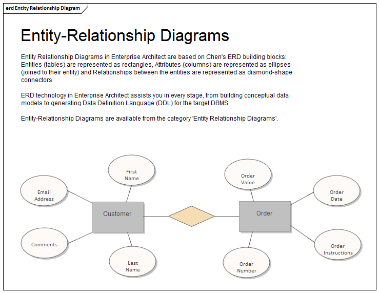
Entity Relationship Diagram Enterprise Architect User Guide

Entity Relationship Diagram Staruml Documentation
Rectangles are named with the entity set they represent.

Entity relationship diagram. The major entities within the system scope and. An associative entity easier to see in the second type of diagram is shown with a dashed outline and connector this type of entity is needed wherever you have many-to-many relationships. An entityrelationship model or ER model describes interrelated things of interest in a specific domain of knowledgeA basic ER model is composed of entity types which classify the things of interest and specifies relationships that can exist between entities instances of those entity types.
The best software tool for drawing Entity-Relationship Diagram is ConceptDraw DIAGRAM vector graphics software with Entity-Relationship Diagram ERD solution from Software Development area which gives the ability to describe a database using the Entity-Relationship model. The process of generating Entity-Relationship diagram in Oracle SQL Developer has been described in Oracle Magazine by Jeff Smith. Commonly the name of the entity serves asthe role name.
Semantic modeling is modeling data structures based on the meaning of these data. Or browse diagrams created by other users. An entity set is a collection of similar entities.
Create Entity-Relationship diagram with online Pony ORM ER Diagram Editor And get generated SQL. The entity-relationship model or ER model is a way of graphically representing the logical relationships of entities or object s in order to create a database. Relationships can relate elements of same entity type.
By clicking on Sign up you agree to our. Entities are represented by means of rectangles. Under Categories click Definition and type a name for the table.
The so-called semantic modeling method nowadays is commonly used in database structure design. Based on the Information Engineering notation. The tuple John CS 2000 describes a relationship.
The ER model was first proposed by Peter Pin-Shan Chen of. Entity set and relationship set. The role of a relationship type may additionally names the purpose of the entity in the relationship.
To create an associative entity in the first style of diagram add an entity shape and a relationship shape and group the two shapes together. Attributes are the properties of entities. ER Diagrams are most often used to design or debug relational databases in the fields of software engineering business information systems education and research.
ER Diagram stands for Entity Relationship Diagram also known as ERD is a diagram that displays the relationship of entity sets stored in a database. When created by business analysts or business users ERDs can be used to understand the business domain clarify business terminology and connect business concepts to database structures. See this article right now to explore more about the ER Diagram field including advantages usages and how-to tips.
Design your SQL database with our free database designer tool. At the very least it includes table names visualized as squares connected by lines that represent primary and foreign key constraints. The enhanced entityrelationship EER model or extended entityrelationship model in computer science is a high-level or conceptual data model incorporating extensions to the original entityrelationship ER model used in the design of databases.
An Entity Relationship Diagram is a visualization of the relationships between tables in a database. An Entityrelationship model ER model describes the structure of a database with the help of a diagram which is known as Entity Relationship Diagram ER DiagramAn ER model is a design or blueprint of a database that can later be implemented as a database. ER diagrams are created based on three basic concepts.
Entity Relationship Diagram ERD is the world-known way to show the logical structure of databases in visual manner. Double-click the shape to open the Database Properties window. What is ER Diagram.
Entity-relationship model ERM or ER model. To work through the example you need an Oracle Database instance with the sample HR schema thats available in the default database installation. In other words ER diagrams help to explain the logical structure of databases.
These entities can have attributes that define its properties. An Entity Relationship Diagram ERD is a visual representation of different entities within a system and how they relate to each other. Entities represent specific concepts or elements involved in a database.
The main components of E-R model are. Any object for example entities attributes of an entity relationship sets and attributes of relationship sets can be represented with the help of an ER diagram. Use the Entity shape to create a table in your diagram.
This type of diagram is. Eg John is value of Student role CS value of Department role of MajorsIn relationship type. For example the elements writer novel and a consumer may be described using ER diagrams the following way.
See the examples of ER diagrams. An entity relationship diagram ERD is a popular type of database diagram that clearly displays the system entities and their internal relationships. SqlDBM offers you an easy way to create an ERD of your database prior to creating an actual one.
Sign up for free. An Entity Relationship ER Diagram is a type of flowchart that illustrates how entities such as people objects or concepts relate to each other within a system. This is an extension to the existing Class Diagram.
An entity relationship diagram ERD is a structural diagram that allows your team to portray relationships between actors in a system. Additional relations for the Information Engineering notation. These can further have specific attributes that further define the overall properties of that said entity.
An entity relationship diagram ERD shows the relationships of entity sets stored in a database. Entity Relationship Diagram Symbols About Entity-relationship Diagram. The Entity Relationship Diagram or ERD is set to help and understand the correlation between the entity sets that are available in a database.
An entity in this context is an object a component of data. Edit in Dokuwiki Edit in Asciidoc Edit in Markdown. From either the Entity Relationship or Object Relational stencil drag an Entity shape onto the drawing.
Entity-relationship diagrams ERD are essential to modeling anything from simple to complex databases but the shapes and notations used can be very confusing. Entities attributes and relationships. An ERD contains different symbols and connectors that visualize two important information.
It was developed to reflect more precisely the properties and constraints that are found in more complex databases such as in. Under Categories click Columns type a name and choose. An Entity Relationship Diagram ERD is a data model describing how entities or concepts or things relate to one another.
Different variants of the entity-relationship diagrams are used as a tool for the semantic modeling.
Entity Relationship Diagram

Er Diagram Erd Definition Overview Lucidchart
![]()
Entity Relationship Diagrams With Draw Io Draw Io

What Is Entity Relationship Diagram Erd

Entity Relationship Diagram Tutorial Gliffy By Perforce

Er Diagram Erd Definition Overview Lucidchart
Entity Relationship Diagrams Learn By Marketing
Entity Relationship Diagram Erd Er Diagram Tutorial


